
Article Plan: Piping Isometric Drawing Symbols PDF
This article details essential piping isometric symbols, offering a comprehensive guide to understanding and utilizing standardized representations for efficient piping system design and documentation.
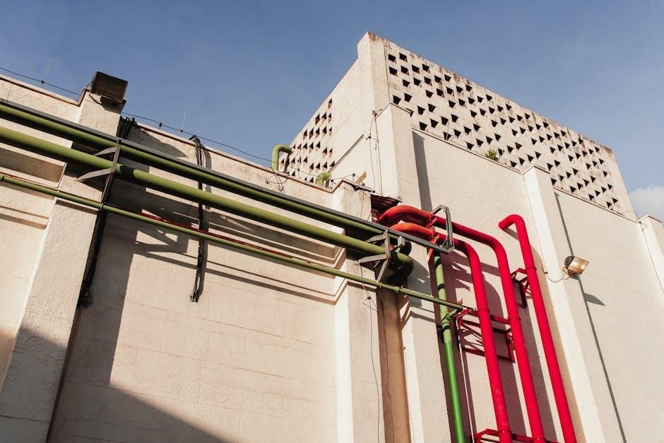
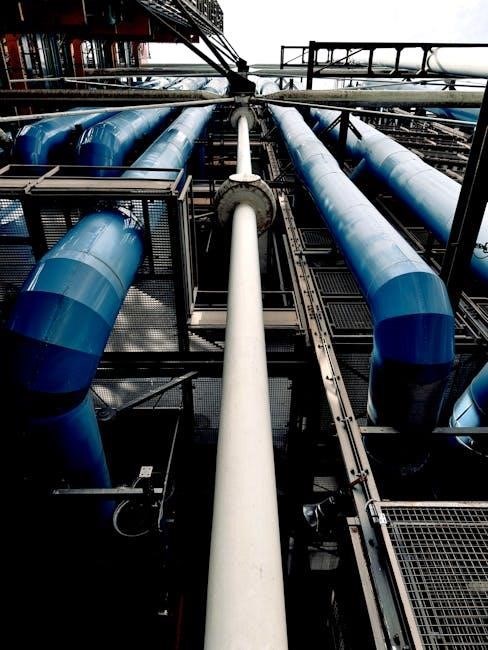
Piping isometric drawings are fundamental to the process industry, providing a clear, three-dimensional representation of piping systems on a two-dimensional surface. Unlike orthographic projections, isometrics visually depict the spatial relationships between pipes, valves, fittings, and other components, making them invaluable for fabrication, installation, and maintenance.
These drawings utilize a 120-degree angle between the three principal axes (x, y, and z), creating a pictorial view that’s relatively easy to interpret. They are crucial for coordinating complex piping layouts, identifying potential clashes, and generating accurate material take-offs. The use of standardized piping isometric symbols is paramount to ensure consistent communication and understanding among engineers, designers, fabricators, and field personnel. Without these symbols, interpreting the drawing becomes significantly more challenging and prone to errors.

What are Piping Isometric Symbols?
Piping isometric symbols are essentially graphical shortcuts – standardized icons representing various piping components. These include pipes, valves, flanges, fittings like elbows and tees, and even instruments. They simplify the depiction of complex systems, allowing designers to create clear and concise drawings.
Instead of drawing each component in full 3D detail, these symbols offer a streamlined visual language. This standardization is critical; it ensures that anyone familiar with the symbols can readily understand the piping arrangement, regardless of the project or company. These symbols facilitate easier interpretation and reduce ambiguity, crucial for accurate fabrication and installation. Resources like PDF guides provide comprehensive collections of these symbols for reference.
The Importance of Standardized Symbols
Standardized piping isometric symbols are paramount for effective communication and collaboration within the engineering and construction industries. Without them, interpreting piping drawings would be subjective and prone to errors. Consistency ensures that a valve symbol in one drawing means the same thing in another, regardless of the designer or location.
This standardization minimizes misinterpretations during fabrication, installation, and maintenance. It streamlines the entire project lifecycle, reducing costly mistakes and delays. PDF resources detailing these symbols act as a common reference point, fostering clarity. Adhering to established standards, often found in piping reference data guides, is vital for safety and regulatory compliance.
Benefits of Using Isometric Drawings
Isometric drawings, utilizing standardized symbols, offer a clear, three-dimensional representation of complex piping systems on a two-dimensional surface. This pictorial view significantly improves understanding compared to orthographic projections. They facilitate accurate material take-offs, crucial for cost estimation and procurement, and simplify pre-fabrication processes.
Furthermore, isometric drawings aid in identifying potential clashes between piping and other plant structures before construction begins, saving time and resources. PDF guides containing piping isometric symbols empower engineers and designers to create and interpret these drawings effectively. They are invaluable for maintenance personnel, providing a visual guide for troubleshooting and repairs.
Common Piping Components & Their Symbols

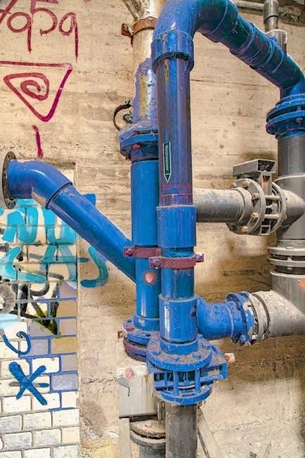
Piping isometric drawings rely on a standardized library of symbols to represent various components. These include pipes themselves, depicted as lines with specific line weights, and fittings like elbows, tees, and reducers, each having unique graphical representations. Valves – gate, globe, and check – are also symbolized distinctly for easy identification.
Flanges, essential for connecting pipe sections, possess dedicated symbols, as do pipe supports crucial for structural integrity. Instruments integrated into the piping system also have specific symbols. PDF resources detailing these symbols are vital for consistent interpretation. Understanding these symbols is paramount for anyone involved in piping design, fabrication, or maintenance.
Pipe Symbols

Pipe symbols in isometric drawings are fundamental, typically represented as straight lines. However, variations indicate pipe size, material, and insulation. Line weight is crucial; heavier lines often denote the primary pipe, while lighter lines show connected branches or continuation. Specific symbols denote different pipe schedules and wall thicknesses.
PDF guides showcase how these lines are modified to represent various pipe configurations. Double lines might indicate insulation, while dashed lines could signify a temporary or phantom pipe. Accurate pipe symbol representation is vital for clear communication and avoiding errors during fabrication and installation. Mastering these symbols is key to interpreting isometric drawings effectively.
Valve Symbols
Valve symbols are standardized representations of different valve types within piping isometric drawings. These symbols clearly indicate the valve’s function and control mechanism. PDF resources detail specific symbols for gate, globe, check, ball, and butterfly valves, among others. Each symbol visually communicates the valve’s operation – whether it’s for isolation, throttling, or preventing backflow.
Understanding these symbols is crucial for interpreting piping schematics and ensuring correct valve selection. Symbols often include directional arrows indicating flow direction. Consistent use of these standardized symbols, as outlined in piping reference data guides, minimizes ambiguity and facilitates accurate system representation.
Gate Valve Symbols
Gate valve symbols in isometric drawings typically depict a rectangular or square shape, representing the valve body, with a sliding gate indicated within. These symbols clearly illustrate a valve designed for on/off service, not throttling. PDF guides showcase variations, often including a handle or wheel representation to signify operability.
The symbol’s orientation indicates the valve’s position within the pipeline. A common convention shows the gate slot parallel to the flow direction when open. Accurate representation, as found in piping reference data, is vital for clear communication. Understanding these symbols ensures correct interpretation of piping schematics and facilitates efficient system maintenance and operation.
Globe Valve Symbols
Globe valve symbols in piping isometric drawings are distinguished by their bulbous or rounded body shape, representing the internal flow path. Unlike gate valves, globe valves are suited for throttling flow, and the symbol often reflects this capability. PDF resources demonstrate variations, sometimes including an arrow indicating flow direction through the valve.
The symbol’s depiction emphasizes the valve’s internal disc and seat arrangement. Accurate representation, as detailed in piping reference guides, is crucial for understanding flow control within the system. These symbols are essential for engineers and designers to correctly interpret schematics and ensure proper valve selection and installation for optimal performance.
Check Valve Symbols
Check valve symbols in isometric piping drawings are characterized by a directional arrow within the valve body, clearly indicating permitted flow direction. These symbols, found in numerous PDF guides, illustrate the valve’s function – preventing backflow. The arrow’s placement is critical for accurate interpretation of the piping schematic.
Variations exist depending on the check valve type (swing, lift, etc.), but the directional arrow remains a consistent feature. Piping reference data emphasizes the importance of correctly depicting this arrow to avoid misinterpretation during construction and maintenance. Understanding these symbols is vital for ensuring system integrity and preventing potential damage from reverse flow conditions.
Flange Symbols

Flange symbols in piping isometric drawings represent connecting points between pipe sections, valves, or equipment. Typically, they are depicted as circles or polygons, indicating the flange face. PDF resources on piping symbols showcase different flange types – weld neck, slip-on, blind – each with slight variations in their graphical representation.
The symbol often includes bolt hole circles to illustrate the fastening mechanism. Accurate depiction of flange details is crucial for fabrication and assembly. Piping reference data guides emphasize standardized flange symbol usage to avoid ambiguity. These symbols are fundamental for conveying connection details in a clear, concise manner, ensuring proper system integration and maintenance.
Fitting Symbols
Fitting symbols in isometric piping drawings graphically represent components altering pipe direction or size. PDF guides detail symbols for elbows, tees, reducers, and couplings. Elbows are shown as curved lines indicating the angle of bend, while tees depict branching connections. Reducers illustrate changes in pipe diameter, often with converging or diverging lines.
Standardized symbols are vital for clear communication during fabrication and installation. Piping reference data emphasizes consistent symbol usage to prevent misinterpretation. These symbols, found in comprehensive piping symbol PDFs, are essential for accurately portraying complex piping layouts. Understanding these representations ensures correct material ordering and efficient assembly of the piping system.
Elbow Symbols
Elbow symbols in piping isometric drawings represent bends in the pipeline, changing the direction of flow. PDF resources illustrate various elbow types – 45-degree and 90-degree being the most common. These are depicted as curved lines, clearly indicating the angle of deflection. Long-radius and short-radius elbows may have slightly different symbol representations, detailed in comprehensive piping symbol guides.
Consistent symbol usage is crucial for accurate interpretation. Mechanical symbols for isometric drawings emphasize black lines for the symbol itself, distinct from the connected pipe. Understanding elbow symbols is fundamental for visualizing piping layouts and ensuring correct fabrication. Detailed PDFs provide visual references for quick identification and proper application.
Tee Symbols
Tee symbols in piping isometric drawings illustrate a pipe fitting with three connection points, creating a branch in the pipeline. PDF guides showcase standard tee representations, typically depicted as a ‘T’ shape, clearly indicating the main run and the branch outlet. Variations exist for reducing tees, where the branch diameter differs from the main run, and these are also detailed in reference materials.
Accurate symbol interpretation is vital for understanding flow paths and component connections. Mechanical symbols for isometric drawings highlight the importance of distinct line weights. Piping reference data emphasizes consistent symbol application for clarity. Mastering tee symbols is essential for accurately reading and interpreting complex piping layouts presented in isometric drawings.
Reducer Symbols
Reducer symbols in piping isometric drawings represent a gradual change in pipe diameter, either increasing (expander) or decreasing (reducer). PDF resources illustrate these symbols as a transition between two different line thicknesses, clearly showing the larger and smaller pipe sizes. Concentric and eccentric reducers have distinct representations, with eccentric reducers often requiring additional notation to indicate the flat side’s orientation.
Understanding reducer symbols is crucial for flow calculations and material takeoffs. Piping isometric symbol guides emphasize the importance of accurately depicting the size changes. Consistent symbol usage, as detailed in piping reference data, ensures clarity and avoids misinterpretation during fabrication and installation. Mastering these symbols is key to interpreting complex piping systems.
Pipe Support Symbols
Pipe support symbols in isometric drawings are vital for illustrating how piping systems are anchored and supported, ensuring structural integrity. PDF guides showcase a variety of symbols representing different support types – shoes, clamps, hangers, and anchors – each with a specific graphical representation. These symbols indicate the method of restraint and load distribution.
Accurate depiction of supports is critical for stress analysis and preventing pipe failure. Isometric pipe support symbol resources detail how to represent supports connected to steel structures or concrete foundations. Standardized symbols, found in piping reference data, promote clear communication between designers, fabricators, and field personnel. Proper symbol usage guarantees safe and reliable piping installations.
Instrument Symbols in Piping Isometrics
Instrument symbols within piping isometric drawings represent control and monitoring devices integrated into the piping system. PDF resources dedicated to piping symbols illustrate these instruments, including temperature sensors, pressure gauges, flow indicators, and control valves. These symbols aren’t merely graphical; they convey crucial process information.
Standardized symbols, detailed in piping reference guides, ensure consistent interpretation across disciplines. They indicate instrument location, tag numbers, and connection types. Accurate representation is vital for process control and safety. Isometric drawings incorporating instrument symbols facilitate efficient troubleshooting and maintenance. Understanding these symbols is essential for engineers and technicians involved in plant operation and modification.
Where to Find Piping Isometric Symbol PDFs

Numerous online resources offer Piping Isometric Symbol PDFs. A readily available 21-page webpage provides detailed diagrams and explanations of common piping components and their isometric representations. Websites specializing in piping reference data, like those offering piping specifications and parts lists, frequently host downloadable symbol guides.
Furthermore, platforms hosting engineering documentation often contain relevant PDFs. Searching for “piping isometric symbols PDF” yields results from various industry sources. Several sites offer free downloads, while others may require registration. Always verify the source’s credibility and ensure the symbols align with applicable industry standards for accurate interpretation and application.
Resources for Piping Reference Data
Accessing comprehensive piping reference data is crucial for accurate isometric drawing interpretation. Several resources provide detailed information beyond just symbols. “Piping Reference Data Guide” offers insights into piping specifications, rules, parts, and, importantly, symbols. Websites dedicated to mechanical engineering and piping design frequently host valuable documentation.
Online platforms and industry associations often provide access to standardized piping data. These resources can include material specifications, welding procedures, and detailed symbol libraries. Exploring resources related to “Valves, Piping and Pipelines Handbook” can also yield valuable information. Remember to prioritize resources aligned with recognized industry standards like ASME or ISO for reliable data.
Understanding Line Weight and Symbol Representation
Interpreting isometric drawings requires understanding how line weight and symbol representation convey information. Symbols themselves are typically depicted with bold, black lines for clarity, representing the component itself. Connected piping is often shown with lighter lines, distinguishing it from the symbol’s core structure.
Line weight variations can indicate pipe size or material. Heavier lines might represent larger diameter pipes or those constructed from different materials. It’s vital to consult the drawing’s legend or accompanying documentation to decipher these conventions. Accurate symbol interpretation, coupled with an understanding of line weight, ensures correct visualization of the piping system’s layout and components.
Tips for Interpreting Isometric Drawings
Successfully interpreting isometric drawings hinges on a systematic approach. Begin by familiarizing yourself with the drawing’s legend, which defines all symbols and line weight conventions used. Trace the piping route visually, following the lines to understand the flow path and component connections.
Pay close attention to the orientation; isometric drawings present a 3D view on a 2D plane. Utilize north arrows or other indicators to establish spatial relationships. Don’t hesitate to cross-reference with other documentation, like piping and instrumentation diagrams (P&IDs), for a comprehensive understanding. Consistent practice and attention to detail are key to mastering isometric interpretation.
Software for Creating Isometric Drawings
Numerous software solutions facilitate the creation of accurate and detailed isometric drawings. Popular choices include AutoCAD Plant 3D, which offers robust piping design and drafting capabilities, and AVEVA E3D, a comprehensive plant design software. SmartPlant 3D is another industry standard, known for its advanced features and integration with other engineering tools.
These programs typically include extensive libraries of pre-defined piping symbols, automating the drawing process and minimizing errors. Some options also support automatic bill of materials generation and clash detection. Selecting the right software depends on project requirements, budget, and user familiarity.
Future Trends in Piping Isometric Representation
The future of piping isometric representation is leaning towards increased digitalization and automation. We can expect greater integration of Building Information Modeling (BIM) with piping design, enabling more collaborative and data-rich project workflows. Augmented Reality (AR) and Virtual Reality (VR) technologies will likely play a larger role, allowing engineers to visualize piping systems in immersive 3D environments.
Furthermore, advancements in artificial intelligence (AI) could automate symbol recognition and drawing creation, improving efficiency and reducing human error. Cloud-based platforms will facilitate real-time collaboration and access to piping data from anywhere, streamlining project execution.